Testing is the
major challenge for any VLSI design either analog or digital. And it’s
something which cannot be ignored or compromised with. Before your design gets
converted to a product you must be very sure about the types of problems which
may occur before hand. Just think of a scenario where I have my design which
performs ALU operations and we will assume that we have made this design a product
without testing it. Though the simulation version of the design may work well
it’s not completely enough to declare the design as fault free. There can be N
number of hardware faults which may occur within the circuit and following
which your design may not work as per your expectation. For digital circuits
hardware testing of your design can be done with FPGA based platforms (Spartan,
vertex, etc). But the question is, are you sure that the FPGA implemented
design will assure fault free designs after you plan to make your product? The
answers is no. FPGA may give you the hardware platform to check your design
functionality but when you want to convert this design of yours into a real
circuit it may have some physical faults(strictly speaking about integrated
circuits).
We will now try and establish an indirect means by which we can test any sequential circuit by making some modification to our design.This example below will help you understand the work better.
FIGURE 1
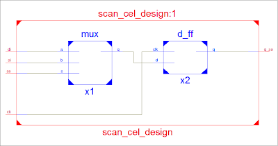
The circuit above is a simple sequential circuit and the gate (circled) has to be tested now. And as you can notice that we cant directly apply inputs to this gate because its not directly connected to the primary inputs. And you can notice that the FF are converted to Scan cells which were previously D-FF. The figure below shows how a D-FF can be converted to a Scan cell which will help us to test any Gate within the circuit which are not directly accessible.

So to test any sequential circuits we have to replace all the D-FF to scan cell as shown in the figure.
Scan Cell Design: It can operate in 2 modes
- Normal mode where the SE(scan enable signal) is LOW and circuit and input is read from primary inputs
- Test mode where SE is high and can use this mode to test the internal gates and input is read from SI(scan inputs)
Step 1: Make SE high (Now the scan cells act like shift registers)
Step 2:Apply test inputs to SI=1 and apply one clock. (this sets the output of first scan cell (X1 in figure 1) to 1.
Step 3: Apply SI=0. and apply one clock cycle .(this shifts output of X1 to X2 and sets output of X1 to 0).
Step 4: Apply SI=1. and apply one clock cycle.(this shifts output of X1 to X2 and output of X2 to X3 and output of X1 to 0)
Now if you observe that after step 4 we have actually set the outputs of scan cell X1 X2 and X3 to 1 , 0 and 1 respectively.
And indirectly we have applied 1 and 1 at the input to out AND gate :-) which we could not do before for any internal gates. The step after applying test input(11) to the Gate under consideration we have to check the Gates response now. Follow the steps below to capture the response of the gate.
Step 5: Make SE=0(normal mode) with primary inputs.
Step 6: Apply once clock cycle (this will make the scan cell X2 capture the response of our AND gate )
Step 7: Make SE=1(scan mode) apply one clock cycle (the caputured response of gate in X2 will we available at scan out. If the Gate is faulty the response will be 0 else it will be one.
The Simulation results for testing the AND gate is given below.
Advantages of Scan Cell
- We can test sequential circuits
- Increases the control ability and make the circuit internal nodes more observable
Have a look at this new course.


Plz post the code also
ReplyDeletesend a mail to asicworld.co@gmail.com with subject "Testing Of Sequential Circuits Using Verilog"
ReplyDeleteIf possible make a video tutorial for this, It can Help us better
ReplyDeleteSure , i will do that soon
Deletecan u explain about sram testing using various fault models
ReplyDeleteWill post this one. Thanks for asking
Deletecan we get isim software for free
ReplyDeletesir i want sample code for the BIST-----as my project is bisr------charantej.peteti@gmail.com
ReplyDeleteplz mail ur details to me
Bist for which circuit?
Deleteplz post me a code for this on pallavi.margade@gmail.com
ReplyDeleteplease send a code to oysatish@gmail.com
ReplyDeletesir ,send me verilog code to suresh888.93@gmail.com
ReplyDelete