Link for the coupons : Here
what is a state machine?
It is a sequential circuit which has some predefined state. The system goes through these states as per the control signal.
Transition takes place for every clock and in some cases it depends on few control signals .
Applications:
State machines are important part of embedded systems. Once we know that a system has to go through a set of well defined states we can design the system and make the machine to act accordingly .
Here i m giving a flow which must be followed to design any state machine.
1. define the states from the specification given.
2. draw state diagram - this must show the states and also transition between the states.
3. decide the flip flop to be used - JK/D/T.. preferably D comes in handy but not necessary in all situations.
4. construct excitation table and get the expression of the FF in terms of its output.
5. draw the circuit diagram from the expression.
6. implement the design in verilog.
Note: number of states will decide the number of FF to be used.
Example. for a 3 bit counter the number of states is 8. and number of FF needed is 3. i.e 2^3=8
Let us start the design for a 3 bit even counter as an example and we will apply all the steps listed above for this specification.
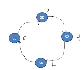
1.Spec: count sequence : 0 > 2 >4 > 6 and repeat
2.State diagram

3. D -FLip Flop selected.
4. Excitation table for D-FF and expression for D0,D1 and D0
From the excitation table write the K-map for D0, D1 and D2 in terms of Q2,Q1 and Q0 respectively.And get the expression of D0,D1 and D2 from the K-map
D0=0
5. circuit diagram :
6. implement the design in verilog:
write a structural code in verilog using "asynchronous D-FF and an xor gate and make connections as shown in the circuit diagram.
CODE:
module counter_state(clk,rst,q
);
input clk,rst;
output [2:0]q;
d_async d0(0,rst,clk,q[0],);
d_async d1(~q[1],rst,clk,q[1],);
d_async d2(q[2]^q[1],rst,clk,q[2],); //d,rst,clk,q,qb
endmodule
);
input clk,rst;
output [2:0]q;
d_async d0(0,rst,clk,q[0],);
d_async d1(~q[1],rst,clk,q[1],);
d_async d2(q[2]^q[1],rst,clk,q[2],); //d,rst,clk,q,qb
endmodule
RTL_schematic:
Simulation results


No comments:
Post a Comment