Pages

Wednesday, 28 August 2013

Verilog code for Barrel shifter


The architecture of the arm 7 is quite unique & is optimized for speed and area. To talk about its bus structure which is patented by Arm called the Amba bus is completely designed by the company itself. Tough its a difficult task to code and design for the entire ARM here is a small module of ARM called the Barrel Shifter as circled in the figure below. The task of the Barrel sifter is to do simple shift & roate operation on the second operands . Shifting a bit to right by one position means the same as to dive the number bu the base 2 . Conversely left shift by one position implies multiplying by 2. So this Shifter reduces the task of the ALU in total. Here is the Verilog code for the Barrel Shifter


module barrel_shifter(d,out,q,c); // Main module of 8-Bit Barrel shifter
  input [7:0]d;
  output [7:0]out,q;
  input[2:0]c;
  mux m1(q[0],d,c);
  mux m2(q[1],{d[0],d[7:1]},c);
  mux m3(q[2],{d[1:0],d[7:2]},c);
  mux m4(q[3],{d[2:0],d[7:3]},c);
  mux m5(q[4],{d[3:0],d[7:4]},c);
  mux m6(q[5],{d[4:0],d[7:5]},c);
  mux m7(q[6],{d[5:0],d[7:6]},c);
  mux m8(q[7],{d[6:0],d[7:7]},c);
  assign out=q;
endmodule

module mux(y,d,c); // Sub module of 8-Bit barrel shifter
  input[7:0]d;
  output y;
  reg y;
  input [2:0]c;
  always @ (c)
  begin
    if (c==3'b000)
      y = d[0];
    else if (c==3'b001)
      y = d[1];
      else if (c==3'b010)
      y = d[2];
      else if (c==3'b011)
      y = d[3];
      else if (c==3'b100)
      y = d[4];
      else if (c==3'b101)
      y = d[5];
      else if (c==3'b110)
      y = d[6];
      else if (c==3'b111)
      y = d[7];
    end
  endmodule


Please Note : Our course is now listed for Udemy training by Industry and leading companies use our courses  :
Analog Design- Intuitive Approach
Rc Circuits Analysis With LT Spice
Basics of Mosfet - Simplified View
Please use these links or share with someone who might be interested.
Note : Author discounts are already applied to these links. 


Tuesday, 27 August 2013

DSP butterfly Unit

Hello friends. You must be aware of the applications of Verilog coding & its significance in different domain. From the last few months i was working on one such use of Verilog in DSP.  Signals & systems   is my all time favorite subject & its the one with lot of applications & used in many products like mobiles, tv, image processing etc. The list is long though  :) We will talk about one such DSP module today " The FFT Butterfly unit " . Before you read this post i suggest you to go through the FFT algorithm (DIT/DIF) so that it will be easy for you to understand the code.  Fast Fourier transform is used to convert a signal from time domain to frequency & this is needed so that you can view the frequency components present in a signals . If you know the frequency components present in a signals you can play with the signals :) Lets say, u want to design a low pass filter and want to decide on the cut off frequency of the filter . If you have the frequency domain details for a signals u can clearly identify the frequency components which u want to retain & the ones which u want to take out. Well let us not discuss this topic in detail here , but if you are still interested than you can refer to my short notes on FFT here:
 Fourier analysis

The figure below shows the FFT implementation using radix 2 algorithm.


this is a 8 point FFT implementation using the butterfly unit, The butterfly unit is the heart of FFT algorithm . From the figure u can see that if we are done with the butterfly unit we are 70% done with the FFT coding.
Okie now lets start the coding for butterfly unit . The back box model of the butterfly will have 2 complex inputs & 2 complex outputs
The second input gets multiplied with the twiddle factor i.e (wr + j wi ) first. So before you start coding you must have the code written for complex number multiplication. Once you are done with the multiplication the next step is to do addition . You can do this by simple CLA (carry look ahead adders) . Output Z1 is obtained by adding the result of multiplication i.e(b1+jb2) * (Wr+jWi) to the first number i.e a1+ja2. And output Z2 is obtained by subtracting the multiplied product with the first number . To put it in mathematical form


Z1r+jZ1i= (b1+jb1)*(Wr+jWi) + (a1+ja2)

Z2r+jZ2i= (b1+jb1)*(Wr+jWi) - (a1+ja2)


If the result is analysed proerly u will discover that we need a complex multiplier ( which has 4 normal multipliers ) & 4 CLA units . To put the process in orderly manner we have to proceed in steps like this
1> read 2 complex numbers & the twiddle factor 
2>multiply 2nd number with the twiddle factor
3> add the product to 1st number to get the first o/p
4>Subtract the product to 1st number to get the first o/p

We are done. Here is the code for the Butterfly unit & the results of simulation & the RTL schematic

CODE:

RTL SCHEMATIC FOR THE CODE:


Link for the coupons : Here

Black Box model:


Please Note : Our course is now listed for Udemy training by Industry and leading companies use our courses  :
Analog Design- Intuitive Approach
Rc Circuits Analysis With LT Spice
Basics of Mosfet - Simplified View
Please use these links or share with someone who might be interested.
Note : Author discounts are already applied to these links. 

Sunday, 25 August 2013

RTL Schematic/Technology schematic

RTL Code:
Hello there. I have been posting about the Verilog coding since a month & just to add to it will deal with the RTL coding today for your design. :)  This post is to completely understand and analyze the RTL code which includes the RTL schematic and the Technology schematic. Having completed your Verilog coding the next step which you all know is to simulate it and verify if the design is working fine. Up to this point in the flow of design process we are still in the software part of coding. To view the code in terms of hardware you will have to move a step ahead and go for “Synthesis “ .  To put it in simple terms synthesis implies the hardware equivalent of your written Verilog code. There are inbuilt synthesis tool which are part of Xilinx & the one which is used is the XST tool. The job of the synthesis tool is to read the code written in Verilog/hdl and with the aid of the library files it has to convert this code to a hardware description netlist. The figure below shows how the process works.

 
Xst tool is quite user friendly to use & it produces the synthesized design just by a few clicks. But one thing is always true, the easier it looks the more complex program is running behind. J we will start now with the Xilinx RTL coding by considering a simple code(D flip flop) and lets try to create both the technology schematic and RTL schematic for it. The Verilog code for D flip flop is given below


module dff(d,clk,rst,en,q,qbar
    );
input d;
input clk;
input rst; // reset
input en; //enable
output q;
output qbar;
reg q;
wire qbar;
assign qbar=!q;
always @(posedge clk)
begin
if(rst) //if reset is high make q=0
q=0;
else if(en)
begin // if reset is low and en is high make ff transparent
q=d;
end
end
endmodule

The objective is not to analyze the code now but to check how the code is mapped to hardware. You can copy this code from here & work in parallel as I take you through the RTL coding. Okie , now change the mode of Xilinx from simulation to implementation mode.  You will find the Synthesis XST option on the right side as show. 


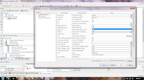
In the Processes pane, right-click Synthesize - XST, and select Process Properties to open the Synthesis
 Options dialog box. Set the Keep Hierarchy option to Yes as shown. 


This is to ensurethat we have the flexibility of viewing the hardware for every module is our design(in case you have many modules in your design). Now just double click on the “View RTL schematic” & you will get a pop up window like this one

Just say OK and the next window will pop up. Select the hierarchical block named dff, and move it to Selected Elements using the Add button, and then click Create Schematic. we are done J the RTL for our code is now generated. It must look like this one


Well now comes the interesting part. J the figure shows the internal and external signals. The border here for this block has a triangle at each edge which indicates that this block is not a primitive but part of our hierarchical design. if you double click on this you will get the exact hardware equivalent of the code . it has a block named “fdre” which is a D flip flop from the library about which we talked about earlier and a "not" gate is present along with it .
   
Now if you place the mouse cursor on any of these elements or the signals the details are displayed. Try it for yourself. For example if you place the cursor on the “fdre” is will display “BLOCK=q,Type=fdre,INT=0”. If you try the same with the signal it will display the number of pins connected to that particular signals. We are now dealing with a simple design (dff)so there are no pins that are invisible. If you try with a complex design you will discover that few pins will be mentioned invisible.
Instead of placing the cursor if you click on a signal you find two symbols indicating the start and end point of the signal.


The RTL schematic generated by the XST tool will be saved in the “.ngr” file format and this schematic is independent of the target device where you want to test your design, in our case its Spartan-3 fpga). If you want to view the exact hardware as it will be mapped to your target FPGA device you will have to go for “view Technology schematic and repeat the same process.


The file format for technology schematic is “.ngc”. Here is how your technology schematic will look like & notice that this one is different from the RTL schematic.


Clearly the input signals are first saved using buffers as it can be noticed. This is necessary because in real time implementation it will be necessary to save the inputs in buffers and then propagate them to the internal design. This avoids the synchronization problems between the FPGA and the inputs devices. 
 Well I hope this post was useful to you, if so do write back to me 

BYE :) 


Link for the coupons : Here

-----------------------------------------------------------------------------------------------------------
EXPLORING THE SCHEMATIC VIEWER WINDOW
-----------------------------------------------------------------------------------------------------------
 The schematic Viewer window is given here with reference to the each icon present to assist you to speed up your RTL coding skills :


1. The schematic window is the main window where you explore your design by adding or removing elements.
2. This toolbar contains the functions specific to the Schematic Viewer.
3. This panel contains two types of information: objects visible on the schematic (instances, pins and signals) and object properties. For example, you can select a BRAM primitive in your schematic and see all its properties, including BRAM initialization values.
Note: You must select the View by Category tab to see this panel.
4. This toolbar contains functions shared by different graphical tools such as Zoom

Zoom options :


Thursday, 22 August 2013

Adding IP Core to your project in Xilinx(verilog)

Adding IP to your project:
Hello guys wasssup J .  I am sure you must have heard of IP, ya you are right its “intellectual property” . To put it in simple terms IP is an already predesigned module which is tested for all possible cases. If you are into a project which demands a complex module & you go on Google searching for those projects for days togetherJ. Well I don’t think its necessary for you to do so as most of your needs are right there with you, puzzled?. Here is a tutorial to use such IP to your design and save your time searching online for codes. Well lets get to some serious talk now. Xilinx provides a simple approach to major projects with a IP package with comes along with the installation of the Xilinx software. These IP packages are very well categorized for selection by a user. To illustrate the IP core I am taking an example of a “complex multiplier “. I am sure that you must have done complex number multiplication on your engineering calculators & its quite easy even to code for it in verilog using multipliers and adders. Lets say I want to multiply two complex numbers a & b to get product p. To put them in mathematical form :
(Pr+pi)=(ar+ai)*(br+bi) ; where
ar =real part of a
ai =imaginary part of a
br =real part of b
bi =imaginary part of b
pr= real part of p
pi= imaginary part of p.
              Now with this simple basics about complex multiplication lets start with Xilinx and see if there is a IP (predesigned module) for complex multiplication. Here is the black box model of our complex multiplier


All you have to do now it to just create a new project with the inputs  ar,ai,br,bi & clk and output as pr & pi and save it. Here is my module :
module complex_mul(ar,ai,br,bi,clk,pr,pi
    );
input [15:0]ar;
input [15:0]ai;
input [15:0]br;
input [15:0]bi;
input clk;
output [15:0]pr;
output [15:0]pi;
endmodule 
 If needed you can change the size of the registers & save it. For simplicity I have used 16 bit numbers. Ok now we are all done, its time to add an IP to your design. Follow the steps given below


>  Right click on your project and click on “new source” you will get pop up window


  >In the pop up window select “IP(Core generator & Architecture Wizard) and give a name to your IP and click “next”


  >You will find one more pop up window. This is where you have all your predesigned IP’s J Click on  “Math functions “ and then within that block click “multipliers” .

  >  Select the first option in multipliers “complex multiplier “ and click next  and then click on Finish .(it will take some time to get added )

After you are done with this you will get a pop up like this :


Click next and you will get one more window , just click on “generate”
                      
    We are done with the IP core generation part. After its generated its just like any other module which can be used in any projects by instantiating the IP. So all we need to do is search for the instantiate code for your IP. The code for instantiating will be present as a file format with extension .VEO. This file will be present in the folder “ipcore_dir” .  Just go to the drive where you have saved your project. In my case its D drive , go to your project folder, and search for ipcore_dir. Here is a snapshot of the folder in my case which will look similar for all projects.


 Open this folder are search for the file with  .VEO extension , open the VEO file and copy the code ,it must be like this one :

add_com YourInstanceName (
            .ar(ar), // input [7 : 0] ar
            .ai(ai), // input [7 : 0] ai
            .br(br), // input [7 : 0] br
            .bi(bi), // input [7 : 0] bi
            .clk(clk), // input clk
            .pr(pr), // ouput [16 : 0] pr
            .pi(pi)); // ouput [16 : 0] pi

Ignore the comments and copy only the instance part and paste it to you main project  as shown here and save it .


Work is done J now just simulate your project and verify the results . I have shown a simple example here by using
ar=1,   ai=2,     br=1,     bi=2 . Take your calculators and multiply these numbers by putting the calcli in complex mode.  The product u will get is pr=-3 and pi= 4 . 
Here is the simulation results


which has the same answer J so its  working fine . did u like this one ? do wrtie to me with your feedback if yes J bye